
Sopwith Camel Models
|
Larry Z. Daily’s Personal Page Sopwith Camel Models |
| During the summer of 2013 I decided to take a bit of a break from model railroading to try my hand at some other subjects and to learn some new techniques. I decided to build a pair of 1:32 scale Sopwith Camels, one equipped with a Clerget engine and one with a Le Rhone engine. Both kits are by Hobbycraft and are generally pretty good, but I wasn’t going to learn anything building them straight out of the box. The photos below document the build. |
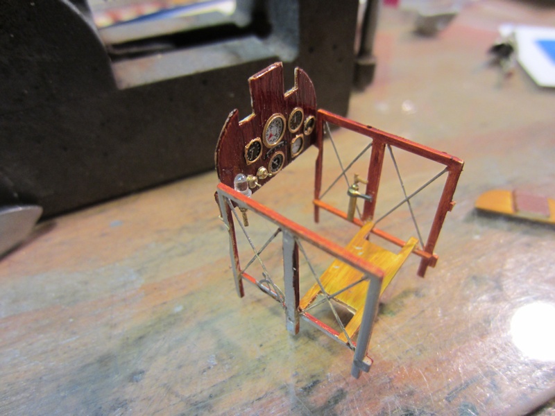 |
(1) The first thing I did was to throw out the stock instrument panels and
scratchbuild my own that more closely matched the prototype. The panel itself is made of
.020 styrene sheet painted to look like stained and varnished wood. I used a base coat of
Model Masters Wood followed by Burnt Sienna oil paint for the grain. Once that dried I gave the
panel a clear coat of Model Masters gloss. The instrument faces and bezels came from Airscale.
I built the magneto switches from scratch. I made the toggle part of the switch from .008" wire.
I dipped the end into white glue (I used Weldbond) to get the rounded shape. The base is a thin
sliver of styrene rod sanded to a rounded shape. I then drilled a #80 hole in the center and
inserted the toggle handle. I also scratched the pulsometer from a headlight insert for an HO
scale locomotive. I retrospect, I think it’s a bit oversized. I used the kit parts for the
framework inside the cockpit. I might have saved myself a lot of pain if I’d scratchbuilt
them; I really had to hack up the fromt to get them to fit properly. I didn’t add much detail
in the cockpit; it really won’t be seen when the model is finished. I added the bracing wires
to the frame, a throttle quadrant on the left (from Tom’s Modelworks) and some sort of pump
thing (excuse the highly technical terminology) on the right. |
 |
(2) Once I got most of the cockpit finished, I was able to join the fuselage halves. In this shot you can see that I’ve drilled out the fuel fillers in the fuselage behind the cockpit and added the caps.I also replaced the kit’s air intake with 2mm aluminum tube. |
 |
(3) In this shot you can see some of the other changes I made. Up front, I’ve added the spent shell chute with 2mm square brass tubing (all the kit had was a square hole). I also replaced the kit seat. The kit part was solid plastic, but the real ones were wicker. The detail set from Tom’s included a seat, but it was flat photoetched metal. What I did to get some depth and something of a woven texture was to cover the parts with desoldering braid. The “leather” edging is styrene rod. |
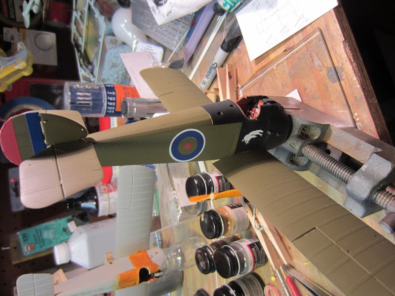 |
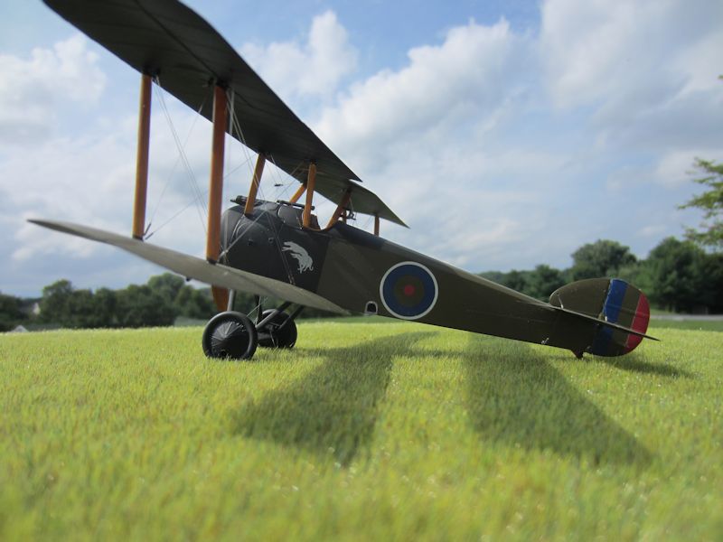
(4) Here, I’ve painted the outside of the fuselage. The real plane that I’m modeling was meant to be a night fighter, so most of the white (in between the blue and red markings) was left off. |
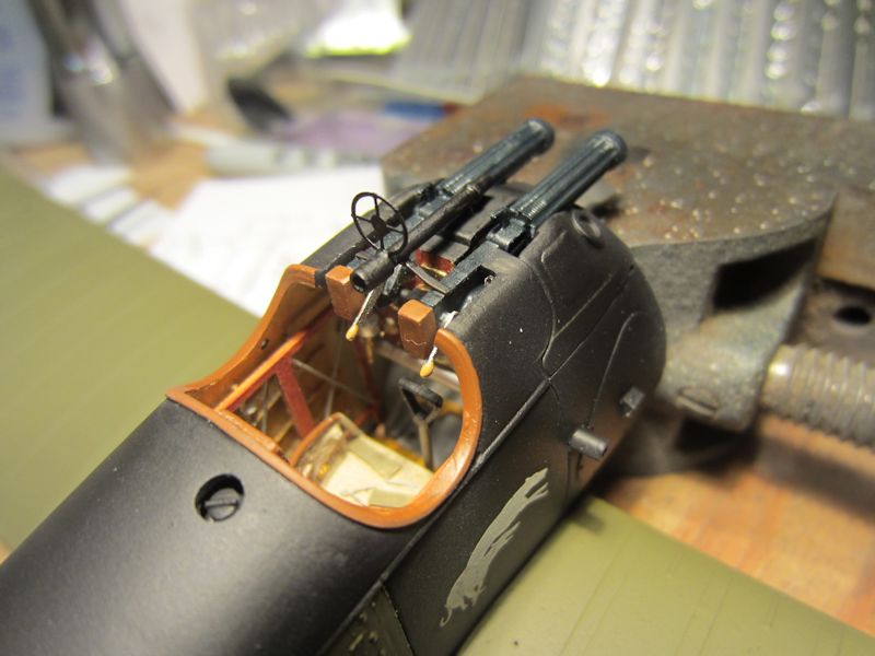 |
(5) Here’s more detail around the “front office”: two Vickers machine guns and the gunsights. I found this arrangement of sights — an Aldis gunsight with a backup ring sight on top — in a book on Google Books. I removed the kit cocking levers (which pointed up and interfered with getting the guns into place) and scratched my own. The Aldis gunsight is also acratchbuilt from brass tubing. |
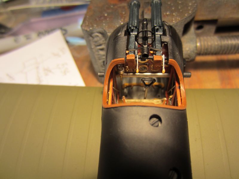 |
(6) Another view of the “front office.” Once the top wing is in place, the view into the cockpit will be limited, so I’m trying to document it thoroughly. |
 |
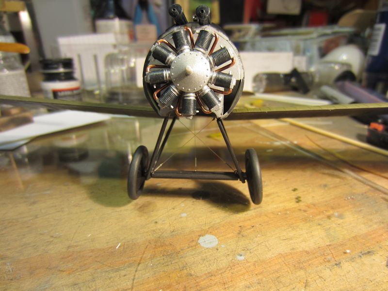
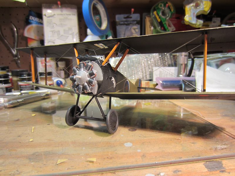
(7) I’ve got this first bird up on her feet. This photo also shows my first attempt at rigging. It looks ok, but I’m not sure that it’s quite right yet. The aircraft seems to be sitting up a bit higher on the right. |
 |
(8) Ok, I’ve got the landing gear straightened out and the aircraft is now sitting level. |
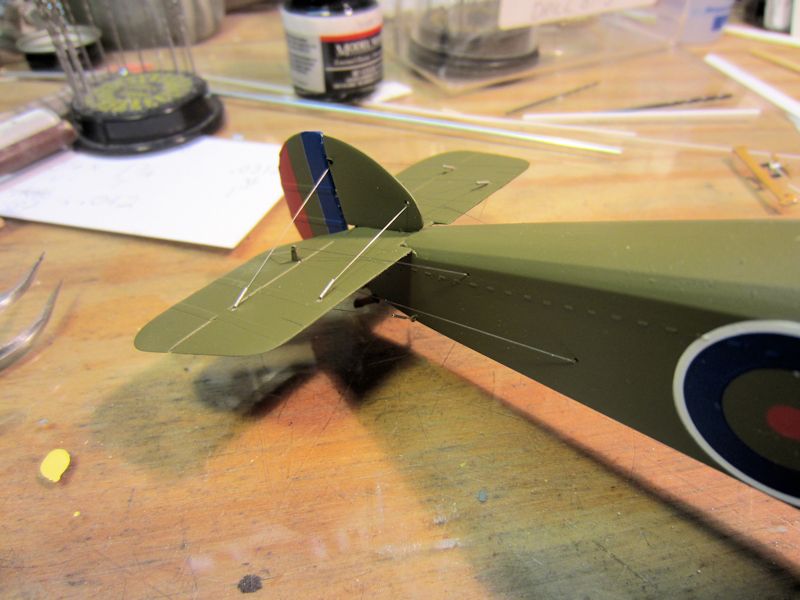 |
(9) The rigging at the back end of the aircraft is now done. |
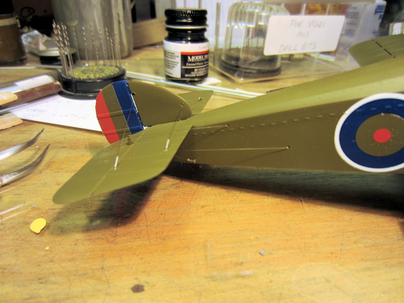 |
(10) Just another view of the completed tail rigging. |
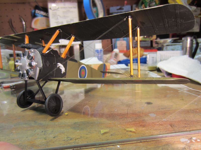 |
(11) In this photo I’ve completed the rigging on the left side of the aircraft. If you look closely, you can see the yellow masking tape holding the right side lines (which are attached to the top wing) out of the way. |
 |
(12) In this photo I’ve completed the rest of the rigging. All that’s left that involves thread is the control lines to the ailerons. |
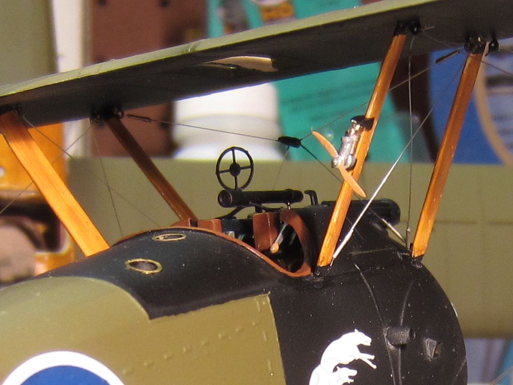 |
(13) The Sopwith Camel had a wind activated fuel pressure pump mounted on one of the cabane struts. This is my representation of the pump. |
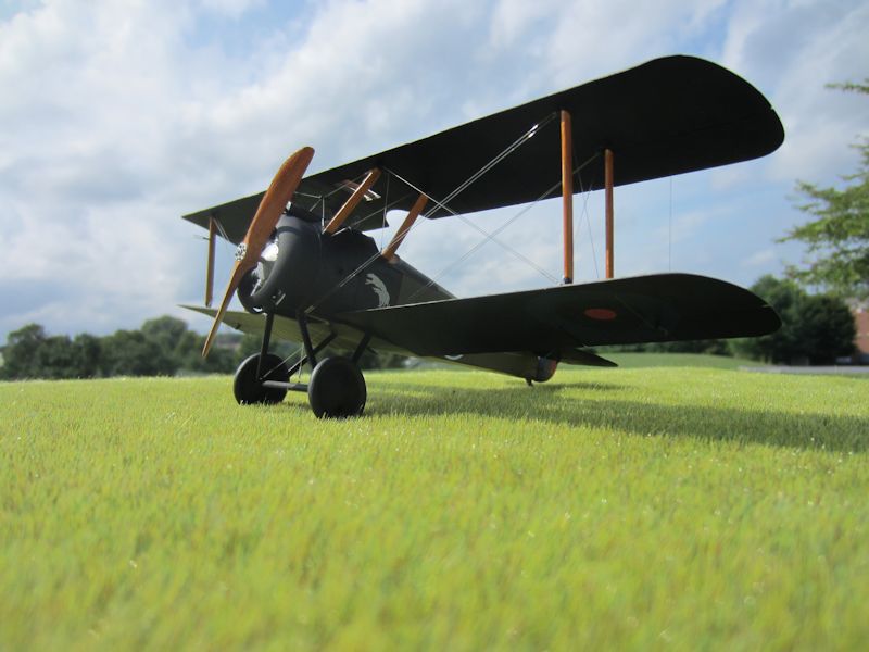 |
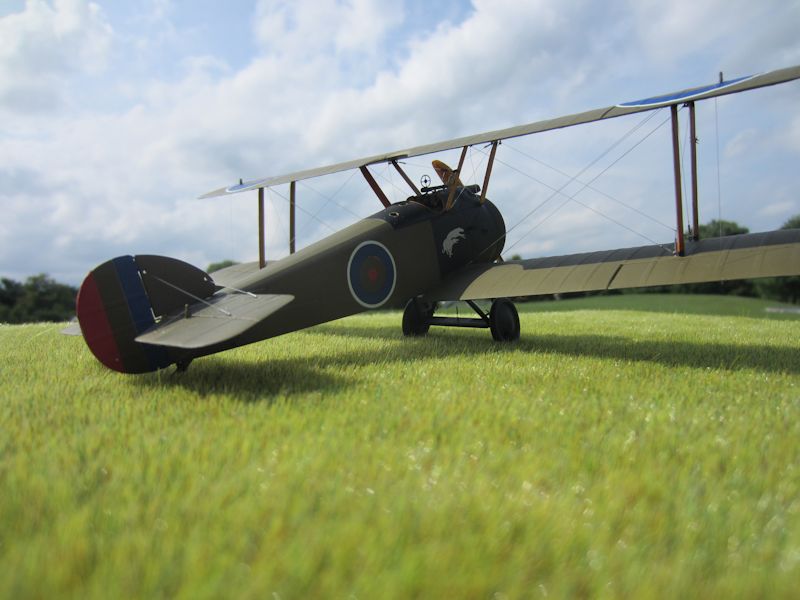
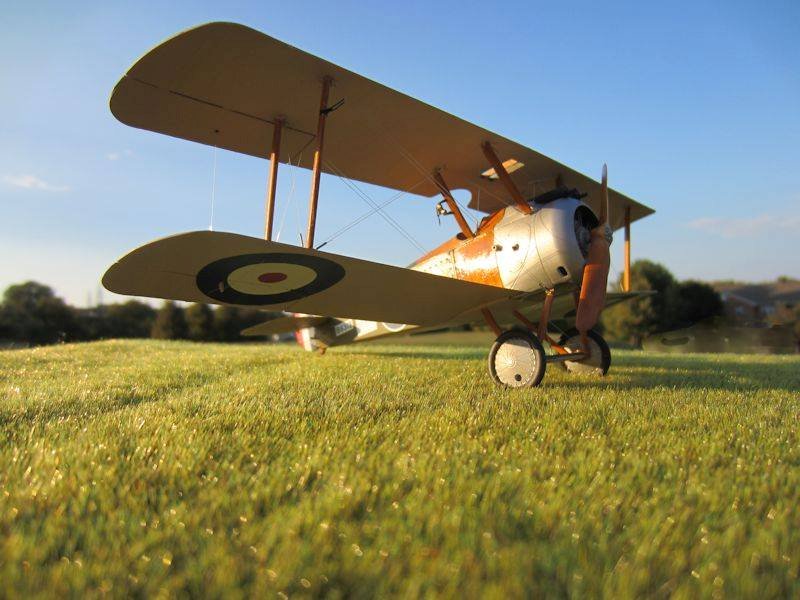
(14) Here are several shots of the completed plane. |
 |
(15) |
 |
(16) |
 |
(17) This model was built to represent the Sopwith Camel flown by Major William G. Barker. While flying Camel B6313 Barker downed 46 enemy aircraft, making B6313 the single most effective fighter aircraft of World war I (I seem to recall reading somewhere that it was the single most effective fighter aircraft ever, but I can’t find that reference now). |
 |
(18) |
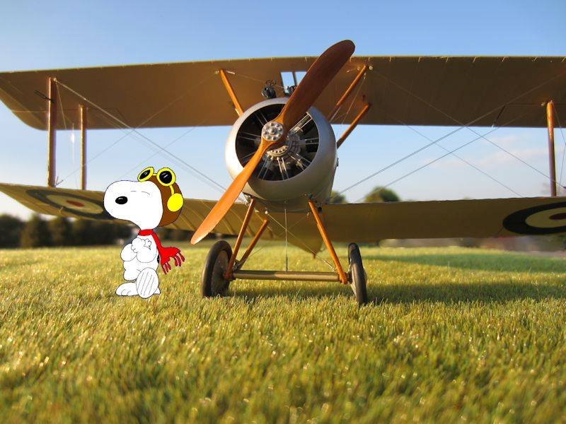 |
(19) OK, I just couldn’t resist. Who better to pose with the best-known Camel but the best-known Camel pilot. |
You can reach Larry at:
Larry Z. Daily.
Visit Larry’s page on Amazon: Amazon Author Page