Accurate Miniatures 1:48 P-51 Mustang
|
Larry Z. Daily’s Personal Page Accurate Miniatures 1:48 P-51 Mustang |
| This model is the second in my Mustang
series. The plan is to build — in 1:48 scale — an example of each variant of the P-51 Mustang flown by the US
in World War II. This build is an Accurate Miniatures P-51. The Mustang, as everyone knows, was developed for the British.
The U.S. Army Air Corps ordered 150 P-51’s in July of 1941. They differed in armament from the British Mustangs; the
U.S. P-51’s had 4 20 mm cannon, 2 in each wing. Before delivery, however, 93 of the aircraft were diverted to Britain.
An additional 2 were used to test the installation of the Merlin engine (which led to the P-51B), leaving just 55 to see
service with the USAAC. The U.S. P-51’s primarily saw service in the North African, Mediterranean, and Italian campaigns. I plan to use the kit decals for this build. The markings are for an aircraft nicknamed Mah Sweet Eva Lea. It was flown by K. F. Bush, who was with the 154th recon squadron, stationed in Tunisia in 1943. Prototype: Model: P-51 Serial number: 41-37322 Nickname: Mah Sweet Eva Lea Pilot: Lt. N. F. Bush Kit: Accurate Miniatures 1:48 P-51 Mustang In addition to the kit, I also used the following aftermarket parts:
|
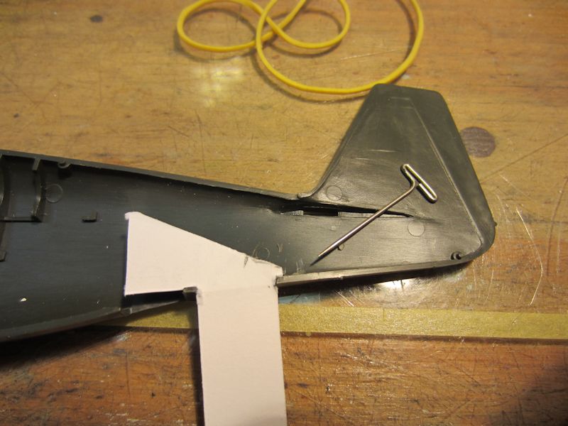 |
(1) I started this build inside the fuselage. The Scale Aircraft Conversions landing gear were
designed for the Tamiya P-51. To use it, I had to replicate the Tamiya mounting system. I started by cutting
one of my old business cards into a template. Then I used the point of a pin to scribe the correct angle into
the inside of the fuselage. The pencil mark on the template marks the front edge of the mounting bracket. |
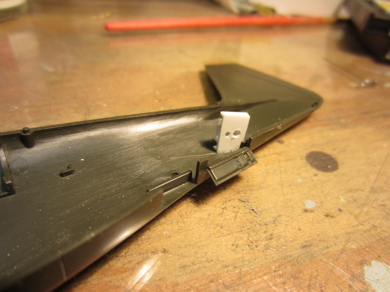 |
(2) Here’s the new mount in the fuselage. The bottom piece is made from sheet styrene. The
corresponding part in the Tamiya kit was .035" thick, so I made mine by laminating .020 and .015 styrene. It’s
.22" front-to-back and .349" side-to-side (at the front of the piece), with a slight taper toward the rear to match
the contour of the fuselage. The forward hole is #57 (.043") and the rear one is #53 (.059), spaced to accept the SAC
part. The top piece is made from .030 styrene with a single #57 hole. I didn’t think the width of the top piece was
critical, so I left about .06" on either side of the hole. I attached the top part to the bottom using .040x.040 strip as
spacers. I did one thing a bit differntly than I did on my A-36 build; I added strip styrene along the edges of the bottom
piece to get a larger gluing surface. After the whole assembly dried, I added it to the fuselage.
|
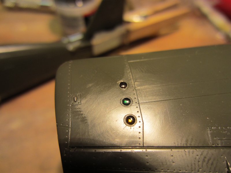 |
(3) As I did with my A-36, I drilled out the formation lights on the wing using a 1/16" drill bit. I cut three lengths
of 1/16" clear styrene rod and polished one end of each. I used Testors Liquid Cement to glue the rods into the holes in the wing
with the polished ends flush with the surface of the wing. After the cement dried, I cut the rods off flush with the inner surface
of the wing and polished the inside ends as well. Then I used (front to back) Tamiya clear red, green, and yellow paint to color the
new lenses. |
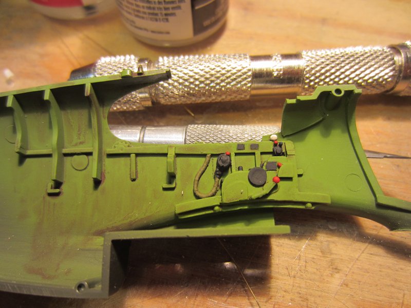 |
(4) Here’s part of the True Details cockpit set added to the left side of the fuselage. The basic color is Model Masters
Interior Green with details picked out in black, red, and white. In prior builds, I used decals for the cockpit stenciling, but once you
close up the early Mustangs by installing the canopy, you really can’t see much. For this build I opted to just paint the stencil
locations with black paint. |
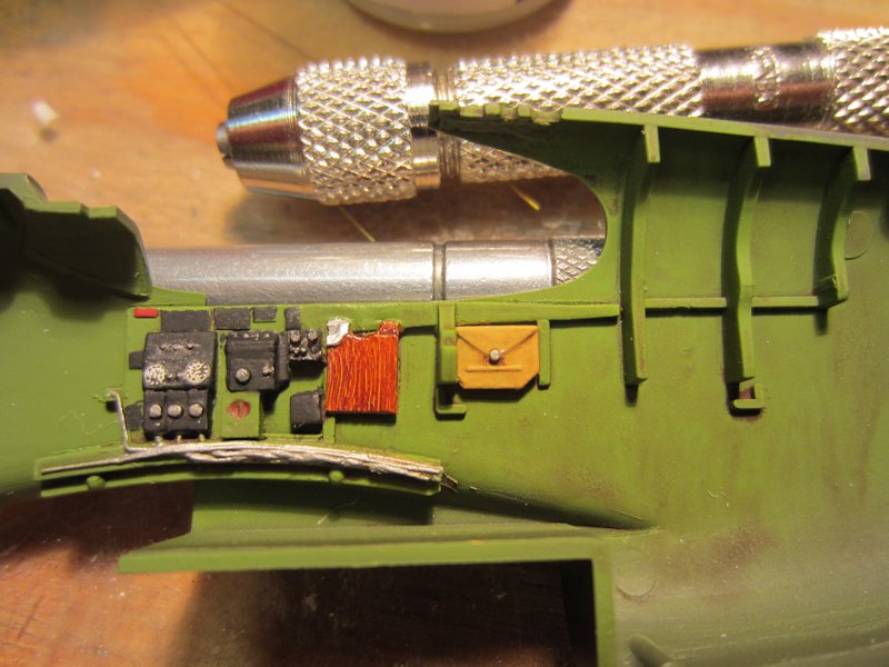 |
(5) Here’s the right side of the cockpit. I weathered all of the cockpit surfaces with a wash made from
burnt umber oil paint and Turpenoid. |
 |
(6) This is the kit instrument panel. I pretty much just followed the instructions here and
applied the instrument decals from the back. |
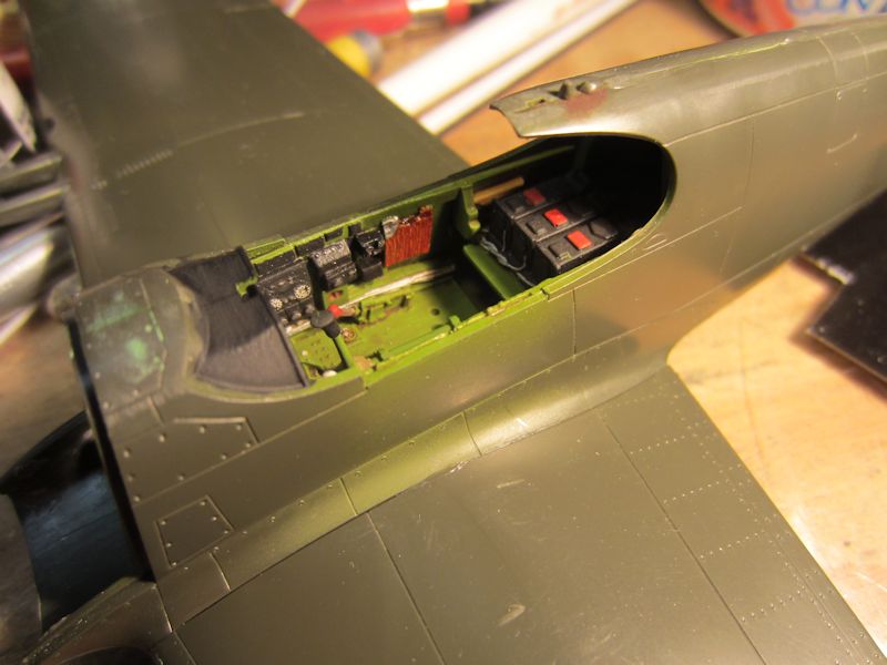 |
(7) I’ve closed up the fuselage at this point and added the wing. I’m pretty happy with how
the cockpit is looking. |
 |
(8) Here’s the left side of the cockpit. |
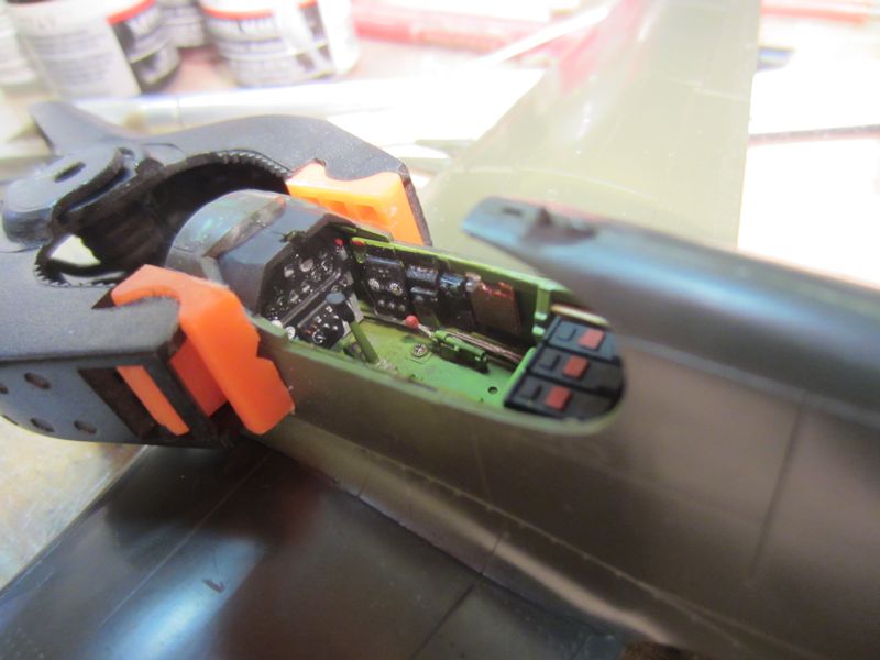 |
(9) Despite the fact that the joint between the fuselage halves had been curing for days, it
still came apart when I inserted the instrument panel. A honking big clamp and a bit of Testor’s cement soon
fixed that. |
 |
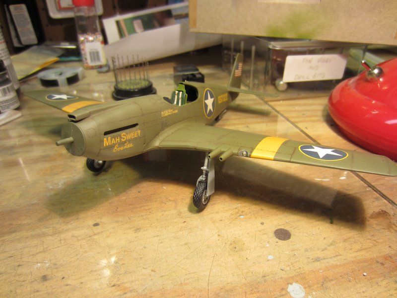
(10) Eva Lea has made it to the spray booth for a coat of Model Masters Neutral Gray underneath and
Model Masters Olive Drab on top. For this build, I decided to paint the main colors first and then add the yellow
theater stripes (or I forgot to paint the yellow first — I’m not saying). |
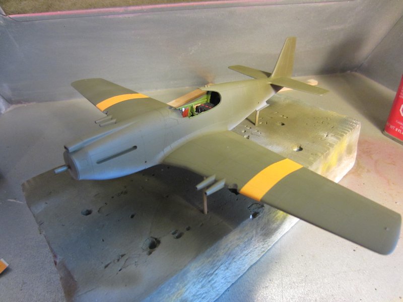 |
(11) I’ve now added the theater stripes. I filled the color cup on my airbrush
about 1/3 of the way with Model Masters Insignia Yellow and then added a couple of drops of Insignia Red.
A few minutes with the airbrush and it was done. |
 |
(12) After a coat of Future, Eva Lea’s getting dressed to go to work. I used the kit
decals. They settled in pretty well using Micro-set and Micro-sol, but I still have a couple of trouble spots
to deal with. |
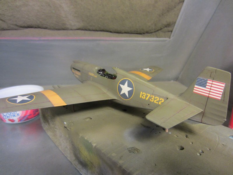 |
(13) In this shot I’ve begun the weathering process. I made a wash of
burnt umber oil paint and Turpenoid and flowed that into the seams on the fuselage and wings.
Once that dried, I gave the whole aircraft a light over spray of Model Masters 1941 Afrika
Khakibraun. |
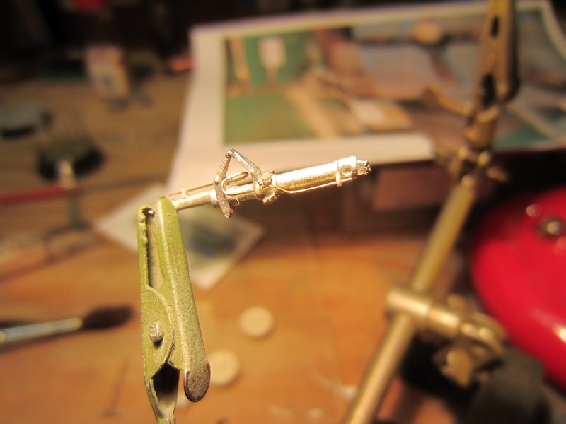 |
(14) I’ve added brake lines to the Scale Aircraft Conversions landing gear struts. The
brackets were made from .010x.040 styrene strip. The rigid part of the brake line was formed from .008 brass
wire and the flexible part from .012 brass wire. |
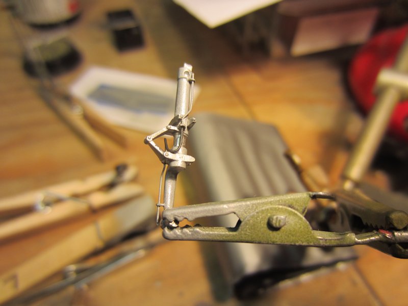 |
(15) Here’s a painted landing gear strut. The main color, meant to replicate
aluminized lacquer, is Testors Model Masters Aluminium with some Neutral Gray added. The flexible
part of the brake line is Polyscale Grimy Black. |
 |
(16) Eva Lea is up on her feet. I really like the Scale Aircraft Conversions
landing gear and UltraCast wheels. In this shot you can also see that I filled in the gaping
hole in the wing where the landing light goes and added an MV Products lens. |
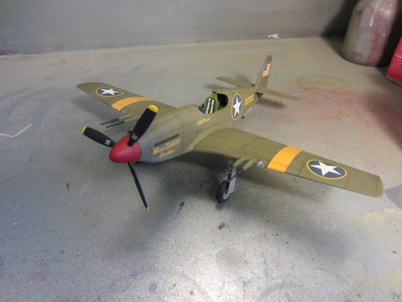 |
(17) I’ve finished up the landing lights (do those parts ever fit correctly?)
and added the prop and spinner. I’ve also mounted the QuickBoost cannon barrels. |
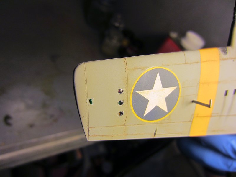 |
(18) Here’s a closeup shot of the lights under the right wing. The nav light was painted chrome silver.
When that dried, I went over it with Tamiya Clear Green. I like how the formation lights look, but it’s a bear when a
decal covers this area. |
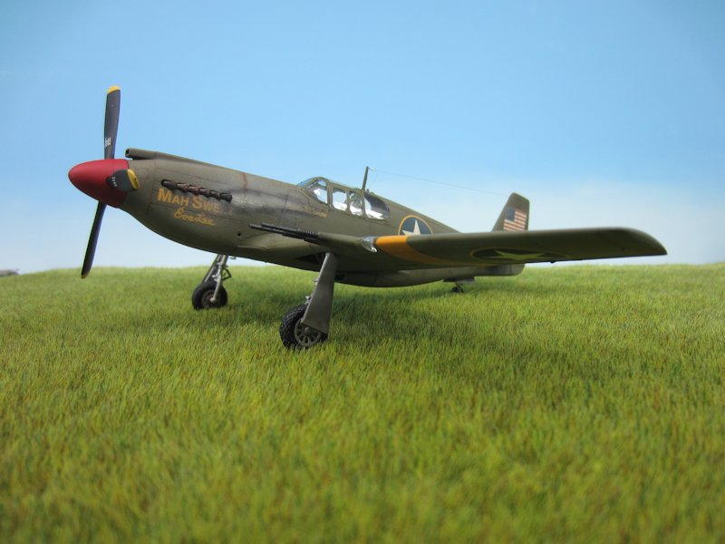 |
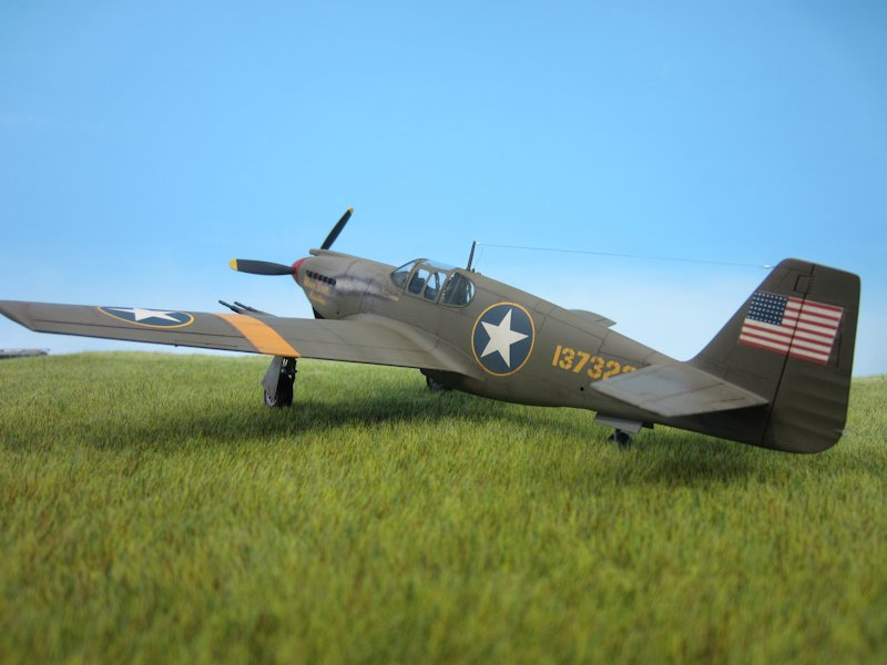
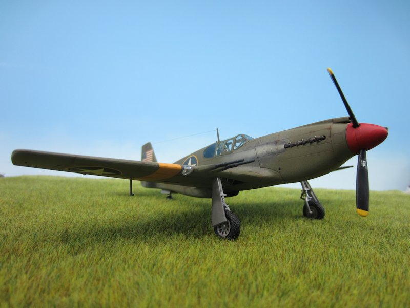
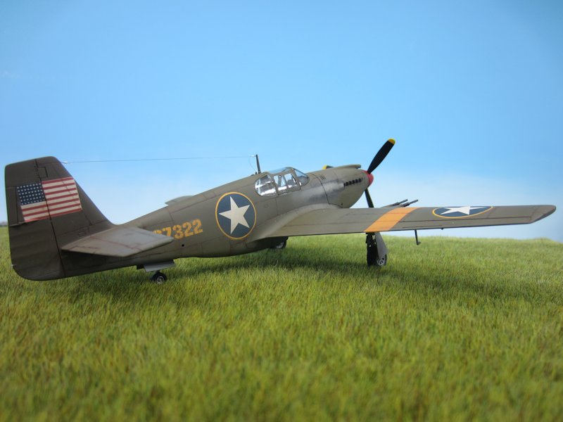
(19) Here are several shots of the finished model. Having learned my lesson with my A-36, the antenna was the
last thing to go on. As I described in my A-36 build, I made two eyelets by wrapping a fine piece of wire around a piece of .008
brass wire and then twisted the ends together. One was mounted in a hole drilled into the vertical stabilizer and the other
into a channel cut into the top of the antenna mast using the edge of a triangular file. The antenna is “invisible” thread.
One end of the thread was run through a small bit of .5mm brass tubing, then through the eyelet on the tail, then back through the
tubing. I snugged that end and fixed it in place with a small drop of ACC. the other end of the thread was passed through another small
bit of .5mm brass tubing, through the eyelet on the antenna mast and back through the tubing. It was snugged up and the loose end pushed
through a hole in the top of the fuselage. |
 |
(20) |
 |
(21) |
 |
(22) |
|
[home]
[trek]
[space]
[camel]
[p-51]
[vega]
[C&O]
[professional]
|